As part of my recent Music Masters degree at Salford University I was required to build an audio plugin or synth using Max/MSP. While contemplating what to create for this project (an FM synth was an early contender), a fellow student (Callum) and I shared some of our previously recorded works. Cal commented how much he liked the crazy effect on a guitar solo I had played for an Elected recording from the early 2000s. The effect in question was the strange-sounding Mutronics Mutator, (this particular example belonged to the producer Jim Abiss) – an effect ubiquitous on recordings from the late 90s and early 2000s (listen to Radiohead’s Paranoid Android guitar solo, etc.). The Mutator uses an envelope/gate follower to modulate a Voltage Controlled Filter (VCF), and four Low-Frequency Oscillators (LFO’s) to modulate the VCF and/or the Voltage Controlled Amplifier (VCA). In simple terms, it’s a synthesizer filter bank that can be applied to any audio source.
 The original Mutronics Mutator 1995 – 2000.
During University IEMPT (Interactive and Emergent Musical Programming Techniques) seminars, we discussed and created various software filters/LFO generators using Cycling74 MAX, so, for this project I decided I would try to create my own version of the aforementioned Mutator effect. It had been years (early 2000’s) since I had used the rack mount version in the studio, so I began by researching, looking at and downloading various images, and grabbing the PDF user manual (Mutronics Limited, 1995 – 2000). Fortunately, the Mutronics user manual proved extremely useful, describing the signal path/routing and information about the various control values, ranges etc.
Making the individual components.
At the time of making, I was still pretty new to the Max programming environment, so I reasoned it might be a good idea to start with some of the more challenging elements. Thus, I opted to build the envelope follower/gate module first. Putting together the effect and making stereo links could wait, after all, that should be pretty easy, and could be put off and dealt with at a later stage (perhaps not my best idea as it would turn out). I found an envelope follower tutorial in the excellent Max software reference (cycling74.com, 2021), from which, by making a few minor adjustments to the provided examples, I managed to create a working envelope and gate module with relatively few problems (Figure 1.). Success, the first three dials of the Mutator (Sensitivity, Attack, and Release) were now functional. Note: at a later stage I would need to create an envelope sweep dial to control the slew (or ramp time) of the envelope hitting the filter (a more or less pronounced filter sweep time).
 Figure 1. Early working version of the Envelope module.
With a functioning envelope module, I could turn my attention to building the LFO module. Previous tutorials discussing oscillators, combined with various online resources (Max forum) made this a relatively straightforward process. Using the original mutator as a guide, I programmed four separate oscillators: Triangle, Square, Saw, and Ramp, and built a selector to switch between the different waveforms (Figure 2.). As with the envelope module, I made a blinking intensity led which would go on to form part of the GUI – more on this later.

Figure 2. An early working version of the LFO module.
Next I began working on the (VCF) filter module (Figure. 3), which proved somewhat challenging. I rebuilt (am currently modifying in conjunction with the LFO module) and simplified this module numerous times. The filter is built from two SVF~ filters placed in series – creating a steeper 24dB rather than a single filter 12dB cut-off/slope. As an aside, the SVF~ filter, while somewhat easy to implement, is limited in terms of frequency response (to around 12.5kHz) and will likely be replaced at some point (biquad?) when I have more competence and time. Frequency cut-off is also sent as a maximum value to the LFO depth, and the envelope/gate inputs (using the scale~ object). A resonance dial was created, and the linedrive object used to provide a more natural sounding logarithmic feel for the various dials – something else which will require extensive calibration upon future testing.
 Figure 3. The evolving Filter module.
Building a GUI.
Having completed early working versions of one side (left) of the modules, I turned my attention to creating a user-friendly interface (GUI). This was imperative at this stage, because even after tidying the Max patcher window was a gigantic mess – a huge tangle of objects and virtual patch cables. I decided I would attempt to closely match the design of the original Mutator – calling this version the Beeline Mutant (a nod to the bee symbol of Manchester).
Being somewhat competent at using Photoshop, I found an online tutorial on creating a brushed metal effect for the mutant’s background and began work. With the unit background image created, all the elements from the original effect were (painstakingly) copied, using various online images as reference (Figure 4.). Although relatively straightforward, recreating the GUI graphically proved immensely time-consuming, and not entirely sure how Max implements graphical elements, I prepared numerous individual components (workable dials, etc.) before porting the background image into Max.
With the graphics complete I discovered that creating a useable dial in Max requires scripting (js), which, under time constraints I deemed too steep a learning curve at this point. To get around this problem, I remade the background image with included blank dial graphic, and overlayed a transparent Max pie dial (I had to tweak the dial radius + 10 degrees to fit). Radio buttons were used to make the various selector switches (which required a few further minor modifications to the background graphic) (Figure 5.).
Returning to the subject of LEDs, this became one of the most time-consuming and frustrating components to build – taking an inordinate amount of time. I used the scale object to calibrate LED blink intensity taking ages to get transparency and colour settings correct. I’m still not entirely sure how I eventually got them to work (every time I reopened the project, the LEDs appeared to function differently). Eventually though, one of the LED’s seemed to work well, and I quickly copied and pasted the object to all the others. Finally, I could get on with the not so simple task of programming the stereo channel links etc.

Figure 4. Creating the GUI in Photoshop.
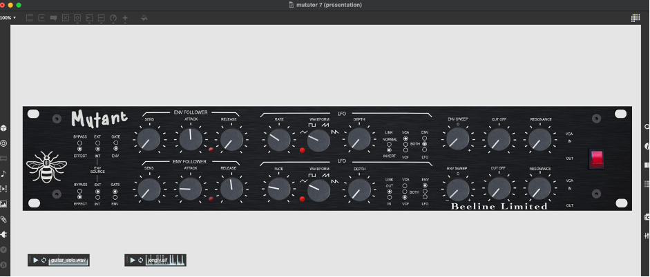
Figure 5. GUI presented in Max, with working dials, radio switches, and troublesome overlayed LED’s
Putting it all together.
This part of the project was akin to painting a floor while being stuck in the middle of a room. Making copies of everything to create a right-hand side channel, renaming all the objects, sends, dials, etc. created mass confusion (transparent dials do not help). On numerous occasions certain functions would cease working due to something as simple as say a random typo, and I would have to roll-back to saved previous versions (there are more than twenty). Many of these kinds of issues were encountered when creating the stereo link functionality – where channel one controls the parameters of both channel one and two together, although I eventually managed to successfully implement both of these functions.
At the time of writing, the Mutant is in the advanced alpha-testing stages. I have yet to complete the VCA/BOTH/VCF switching (there is a problematic working test version – see painting floor analogy). Alongside this, other MA projects and commitments (notably driving round the country recording a Podcast) have eaten into my available time. That said, as my competence in programming Max grows, the Mutant will be completed.
Thanks again to Adam Hart for his help with the creation of this software effect.
User Manual:
Mutant Manual
Refs
Mutronics Limited. (2000). Manual. Retrieved from http://www.mutronics.co.uk/multimedia/manual.pdf
MSP Dynamics Tutorial 1: Envelope Following. (n.d). Retrieved from https://docs.cycling74.com/max7/tutorials/09_dynamicschapter01